4. Sketching and Musical Gesture
While touchscreen interaction and built-in sensors can benefit preexisting text-based music programming systems, it was clear fairly immediately that typing text code using a virtual keyboard was a poor experience. Yet it warrants further study to explore the application of touch interaction to the programming of musical software. Is there a touchscreen-based programming system that, in some instances, one might want to use over a desktop-based system? What might such a system look like and how would it work?
To begin to answer these questions, we propose a new model for touchscreen interaction with musical systems: the combined use of stylus-based handwriting input and direct touch manipulation. A system using this model might provide a number of advantages over existing touchscreen paradigms for music. Stylus input replaces the traditional role of keyboard-based text/numeric entry with handwritten letters and numerals. It additionally allows for modal entry of generic shapes and glyphs, for example, canonical oscillator patterns (sine wave, sawtooth wave, square wave, etc.) or other abstract symbols. The stylus also provides graphical free-form input for data such as filter transfer functions, envelopes, and parameter automation curves. The use of a stylus for these inputs allows more precise input and thus more precise musical control. Multitouch finger input continues to provide functionality that has become expected of touch-based software, such as direct movement of on-screen objects, interaction with conventional controls (sliders, buttons, etc.), and other manipulations. Herein we discuss the design, prototyping, and evaluation of a system designed under these principles, which we have named “Auraglyph.”1
Motivation
The initial insight leading to this work was that numeric and text input on a touchscreen might be more effectively handled by recognizing hand-drawn numerals and letters, rather than an on-screen keyboard. Recognition of handwritten numerals and text is a classic problem of machine learning research, with many historical and contemporary innovations [6]. Crucially, a number of off-the-shelf implementations of handwriting recognition techniques exist, allowing for rapid prototyping of applications using the technology without extensive research, development, refinement, and testing of machine learning algorithms, such as LipiTk [7] and the $1 Recognizer [11].
We soon realized that we could use handwriting recognition to analyze a substantial number of handwritten figures and objects beyond just letters and numbers. A user might then draw entire object graphs and audio topologies to be realized as an audio system or musical composition by the underlying software application in real-time. Handwriting recognition might also be used for modal input of standard figures in computer music, such as amplitude envelopes, filter frequency responses, staff notation, and audio mix automation.
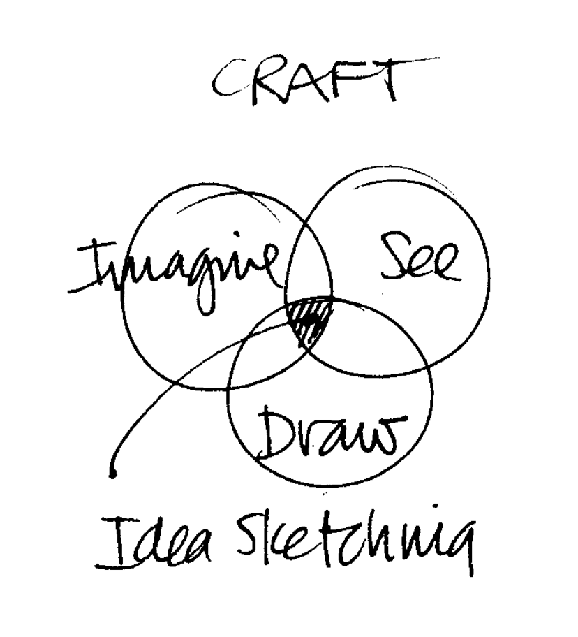
Manual sketching has been identified by many as an integral process to a number of creative endeavors. Buxton has cited sketching as the “archetypal activity of design,” necessary to quickly and inexpensively explore a variety of concepts and ideas and share these among collaborators [3]. Verplank’s writings position sketching in a simultaneous feedback cycle of imagining an outcome and seeing it manifest (Figure 1.1), likening the process to “the experience of any craftsman in direct engagement with his materials: imagining, shaping, seeing all at the same time” [9]. The art critic John Berger expounded on the exploratory nature of quick drawings and sketches, stating that “each mark you make on the paper is a stepping stone from which you proceed to the next, until you have crossed your subject as though it were a river, have put it behind you” [1].
hese processes are similarly applicable to the design of interactive musical software. Evidenced by the research of Garcia et al. in computer-based support tools for compositional sketching [4, 5], handwritten planning is a vital component of many compositional processes, whether the resulting musical product is electronic, acoustic, or both. More generally, writing and drawing with a pen or pencil on a flat surface is a foundational expressive interaction for an incredible number of individuals; this activity is continuously inculcated from early childhood around the world. Sketching, as a natural interaction for expressing ideas in the real world, might be apt for realizing them in a virtual world. Auraglyph seeks to apply this to the context of computer music and audio design. By shortening the distance between abstract musical thought and its audible realization, computer-mediated handwriting input might arm composers to more effectively express their musical objectives.
Another distinct advantage of this interaction framework is the ability to evaluate and run handwritten constructs in real time. As in Landay’s SILK, sketches in Auraglyph are reified into entities specific to the system (e.g., a drawn object might be converted to a sine wave generator, or a timer). These entities can then present controls and interfaces for direct touch manipulation or stylus gestures, customized to that object type or mode. This level of real-time creation and manipulation affords a composer or programmer performative control similar to live-coding.
Lastly, the availability of direct touch control enables a powerful two-handed interaction.2 Rather than simply using the stylus as an “extra finger,” this framework could design certain interactions for pen use and others for hand usage. Two-handed or “bimanual” interactions arise in a variety of commonplace and specialist activities, such as driving a manual-transmission vehicle, technical drawing, artistic practices, and in particular the performance of many musical instruments. Two-handed interaction can be a powerful technique to create interfaces that are accessible to new users, provide additional functionality that can be discovered over time, and are amenable to progressive degrees of user proficiency. As a user gains more experience with such an interface, he or she might gradually grow more capable with the tool overall. Sellen, Guiard, and Buxton have argued that “two hands can be a more efficient and effective approach to interaction” with regard to both time taken and cognitive effort, though careful design is needed to ensure a two-handed interaction does not turn out worse than a single-handed one [2].
Auraglyph was originally developed on tablet hardware that does not support separate pen input; the user instead employs a conductive pen-shaped object that appears to the system as another finger. The difference between pen and touch input is primarily conceptual, existing in the design intent of the software and the mind of the user. Newer tablet products such as the Microsoft Surface Pro or Apple iPad Pro support separate input paths for pen and touch, allowing these to be explicitly differentiated in a software implementation. This technology might further augment the principles of two-handed interaction present in Auraglyph; however at this time such developments are left to future research.
Principles
With these ideas in mind, several principles underlie and support the design of Auraglyph.
Stylus input is used for original input of structures. These structures are then converted from raw pen strokes to objects in the system of a specified class and carrying adjustable characteristics. The class is determined by the form of the raw input and the current mode the software is in. For instance, drawing a circle form in the base mode of the app creates an audio generator node. Drawing an arbitrary figure in the waveform editor creates an oscillator with that waveform.
In some cases the raw pen input is left as such, as in the case of “freedraw” mode or the waveform editor. In these cases the system representation of the structure differs little or not at all from the drawn form, and no further conversion is necessary or appropriate.
Touch input is used to further adjust and parameterize these structures. Base-level nodes can be freely moved around the canvas. Parameters of oscillators and filters can be adjusted using a slider-like mechanism.
Input modes are used to differentiate and separate stylus and touch input that can be easily confused by the system or that might lead to excessive input error. For instance, a separate free-drawing input mode is used to allow users to draw freeform figures without them being analyzed by the handwriting recognizer. A select mode allows users to select multiple structures for batch processing.
The provision of multiple input modes can be seen as a compromise between some ideal of design purity and usability. The use of different modes implies the user must perform at least one extra action and additional mental processing before carrying out any particular desired interaction, inhibiting the user’s flow between different activities within the app. In exchange for this additional effort, the user is given a greater breadth of possible activities.
Real-time feedback is used to constantly inform the user of the results of their decisions and modifications to the application. Fast and constant feedback on programming decisions is necessary in the context of creative coding. Often code and systems will be developed without a particular goal in mind; or, an aesthetic idea, once executed, will prove to be ultimately undesirable. As exemplified by the Audicle and reacTable systems, a programming environment that provides real-time feedback on how a program is being executed will better arm a creative coder to explore a breadth of sonic opportunities.
Design
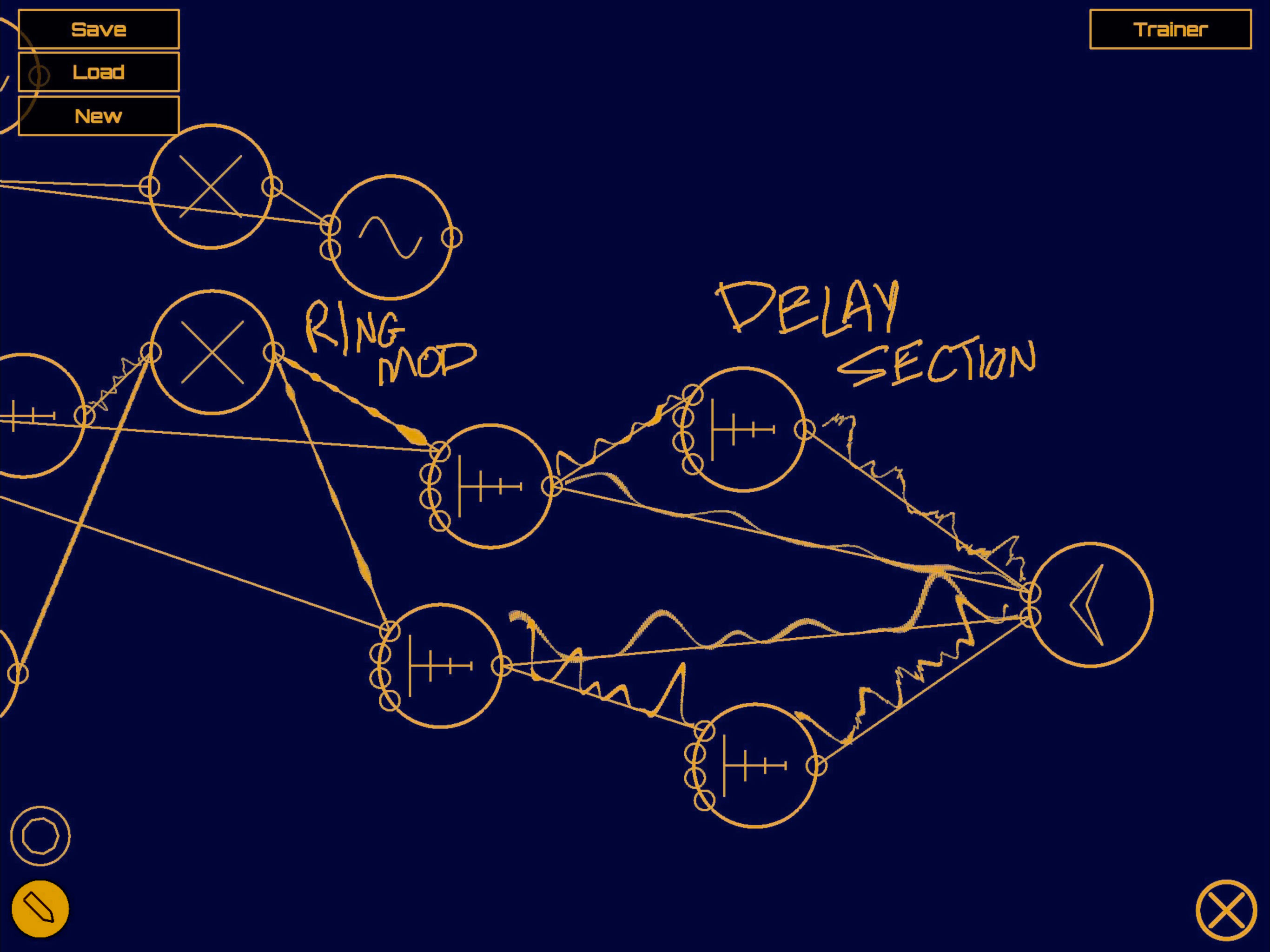
A user interacts with Auraglyph with a stylus and with touch. The basic environment of Auraglyph is an open, scrollable canvas, extending infinitely in two dimensions, in which the user freely draws. Pen strokes are reified into interactive nodes (such as unit generators or control rate processors), which can then be linked by drawing connections between them or parameterized with touch gestures. The nodes the user has drawn, the parameters they have been assigned, and the connections drawn between them are called an Auraglyph program (Figure 1.2), and determine the overall sound that is produced.
The system’s interpretation of the user’s gestures in this basic environment depends on the current input mode, which the user can select from a set of buttons on the bottom left of the screen. Current supported input modes are node and freedraw. The node mode, described in the next section, allows for creating audio and control processing nodes, making connections between them, and adjusting their parameters. The freedraw mode allows users to directly draw onto the canvas. Strokes in freedraw mode are left as is for the user to annotate or decorate their program.
A few basic gestures apply to the canvas regardless of the input mode. A two-finger drag gesture will scroll the canvas in the direction of the drag. A two-finger pinch will zoom in or out.
Node Mode
In node mode, after a user completes a pen stroke (a single contour between touching the pen to the screen and lifting it off the screen), it is matched against the set of base node types, via a handwriting recognition algorithm (discussed in Handwriting Recognition). These nodes include an audio rate processor (unit generator) or control rate processor (see Nodes). If the stroke matches an available node’s glyph, the user’s stroke is replaced by a node of that type. Unmatched strokes slowly fade away, indicating a failure to match.
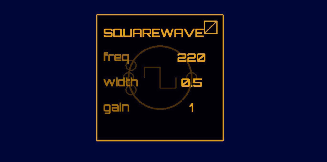
SquareWave node. The
editor can be “pinned” open by pressing the button in the upper-left
corner; unless pinned, an editor window will automatically close when
the user touches or draws anywhere outside the editor
window.apping and holding a node will open a list of parameters for that node (Figure 1.3). If the parameter is numeric, the user can press its value and drag up or down to adjust it by hand. Typical parameters are adjusted on an exponential scale (e.g. frequency or gain), but a node can specify if some parameters are to follow a linear scale. A tap on the parameter name opens a control into which writing a number will set the value. This value can then be accepted or discarded, or the user can cancel setting the parameter entirely (Figure 1.4). Tapping outside the editor popup will cause it to be closed; however, by toggling the “pin” button in the upper left corner of an editor window, that editor will be pinned open until the user un-pins it.
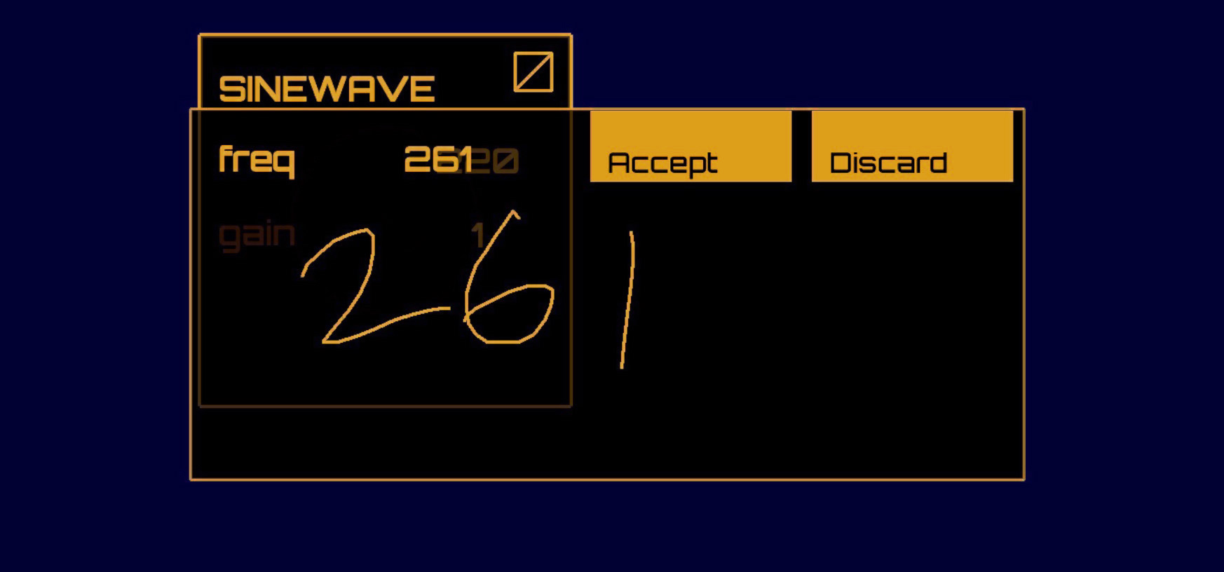
freq parameter of a
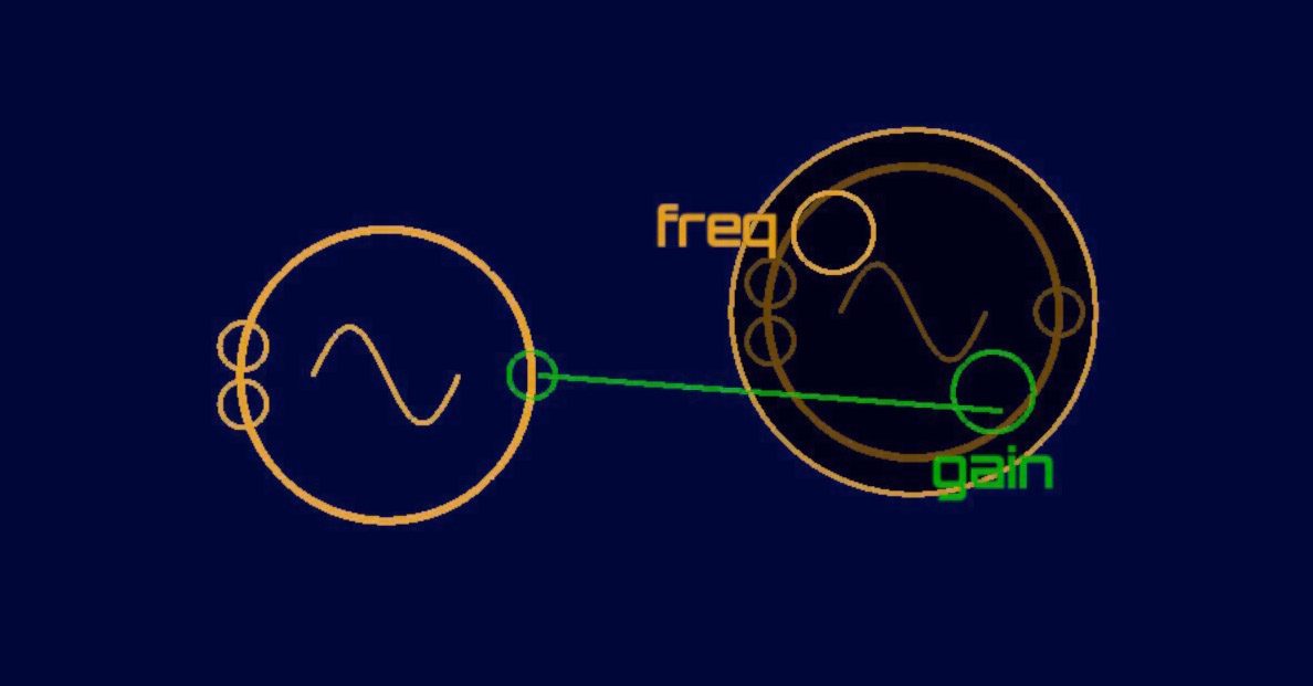
unit generator with handwritten numeric input.node may have multiple inputs and/or outputs. These appear visually
as small circles, or ports, on the perimeter of the object.
Drawing a stroke from an input port to an output port, or vice versa,
forms a connection between those two objects. For example, connecting a
SawWave node’s output to the freq input port
of a SineWave node creates a simple FM (frequency
modulation) program, with the sine as the carrier wave and the sawtooth
as the modulator. Most objects only have one output source, but an input
node may have several destinations within that object (e.g. frequency or
amplitude of an oscillator node, cutoff or resonance of a filter). When
dragging a new connection to a destination node, a pop-up menu appears
from the node to display the options a user has for the input
destination (Figure 1.5).
any, though not all, input ports on a given node are mirrored in the node’s parameter editor, and vice versa. This allows and even encourages extensive modulation of any aspect of a node’s operation, including both conventional and atypical modulation structures. It is fairly easy to create any classical frequency modulation topology, for instance. Less common modulation schemes, such as extreme modulation of delay line lengths or the integration of ring modulation into unusual places, are also available for experimentation.
One exception, the ADSR node does not have input ports
for its attack, decay, sustain,
or release parameters; these must be edited manually
through the node’s parameter editor. These exceptions are mainly to
reduce visual clutter on the node itself and the port selection pop-up
menu. A full list of node types, including their respective parameters
and input ports, is listed in Appendix [appendix:nodes].
Audio-rate connections display the audio currently being transmitted through them, and control-rate connections display a “ping” animation whenever a new value is pushed through them. Audio waveforms are normalized by their effective amplitude and then rescaled logarithmically. This ensures that a diverse range of audio amplitudes can be shown without any one of them overwhelming the visual field. Control-rate pings are also scaled logarithmically according to the value of the control signal. These displays allow visual debugging of the current program and also provide insight into the effects of individual parts of the program.
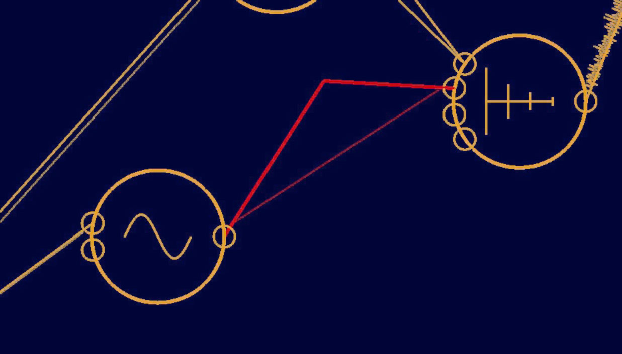
Nodes and freehand drawings can be moved around on the canvas by touching and dragging them, a familiar gesture in the touchscreen software ecosystem. While dragging an object, moving the pen over a delete icon in the corner of the screen will remove that object, along with destroying any connections between it and other objects. Connections can be removed by grabbing them with a touch and then dragging them until they “break” (Figure 1.6). The entire canvas may be scrolled through using a two-finger touch, allowing for programs that extend well beyond the space of the tablet’s screen.
uraglyph fully supports multitouch interaction. Pinning multiple editor windows open allows the user to adjust as many parameters at once as they have free fingers. Multiple connections can be made or broken at the same time, allowing for synchronized changes in a program’s audio flow.
Nodes
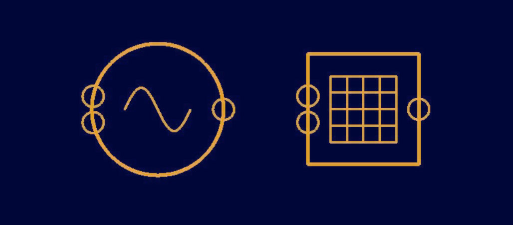
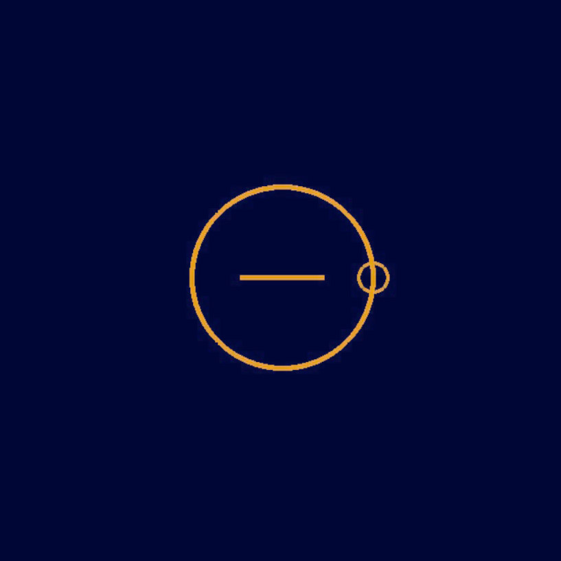
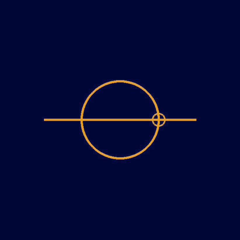
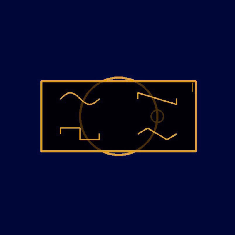
Two base types of nodes can be drawn to the main canvas: audio-rate processors (unit generators; represented by a circle) and control-rate processors (represented by a square) (Figure 1.7). Unit generators currently available include basic oscillators (sine, sawtooth, square, and triangle waves, plus hand-drawn wavetables), an ADSR envelope, filters (resonant low-pass, high-pass, band-pass), white noise, arithmetic operators, feedback delay, a compressor, and audio input and output nodes. Control-rate processors include timers, discrete time-step sequencers, a pitch-to-frequency converter, spatial orientation input, and basic math operators. After creating a base object, a scrollable menu opens to allow the user to select the desired node sub-types (Figure 1.8).
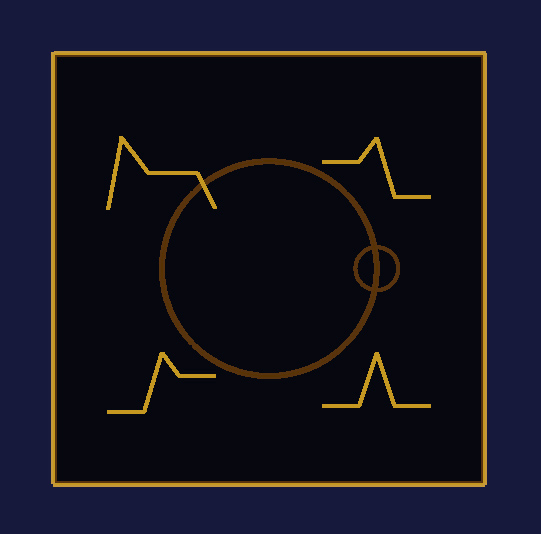
ome nodes have more advanced needs for modifying values beyond the
standard parameter editor. The Waveform oscillator brings
up a large input space for precisely drawing the desired waveform. The
Sequencer object brings up a standard discrete step
sequencer editor that can be expanded in number of steps or number of
outputs per step. A full list of node types is provided in Appendix [appendix:nodes]. Two distinctive
nodes are discussed here.
Waveform
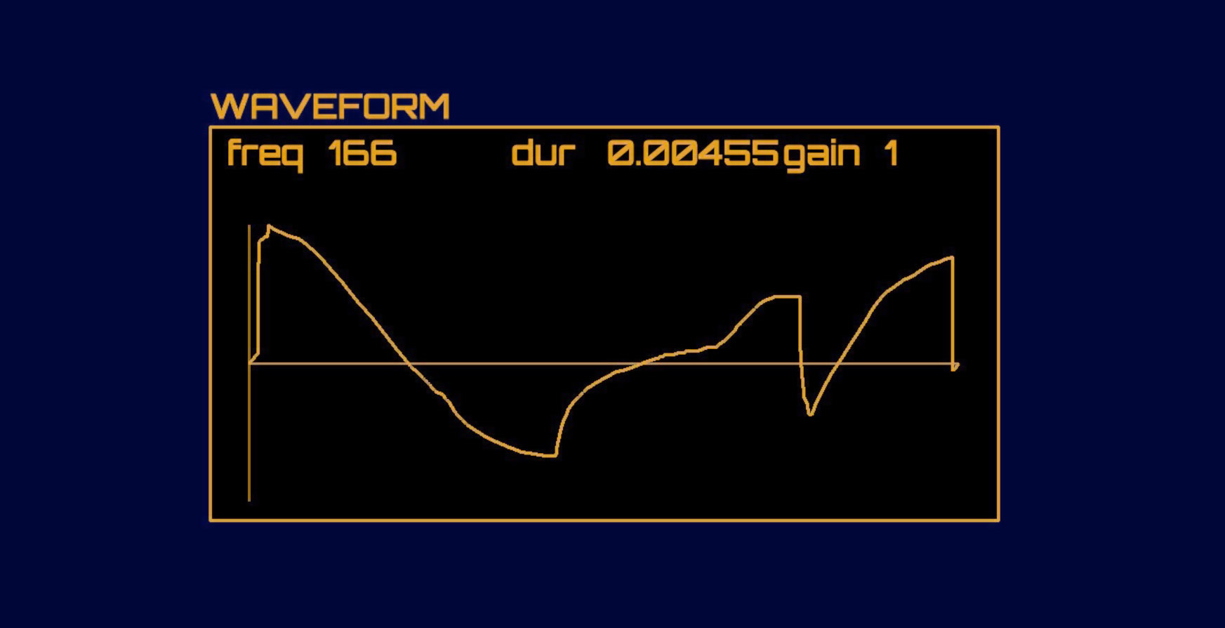
Waveform
node.he Waveform node synthesizes a user-defined cyclic
waveform. Editing the Waveform node will open an editor
window that allows the user to modify this waveform using the stylus
(Figure 1.9). As the user modifies the
waveform, its output is dynamically updated. The icon shown on the node
is also adjusted to match whatever user waveform it is currently
generating. Waveform nodes can be driven by other
oscillators, or even other Waveform nodes, to create
intricate hierarchies of custom waveform modulation. A
Waveform node can also be used as a low frequency
oscillator to effect long term change of a modulated parameter of some
other node. Internally, Waveform nodes use a 1024-point
wavetable and linearly interpolates values lying between two points in
the table.
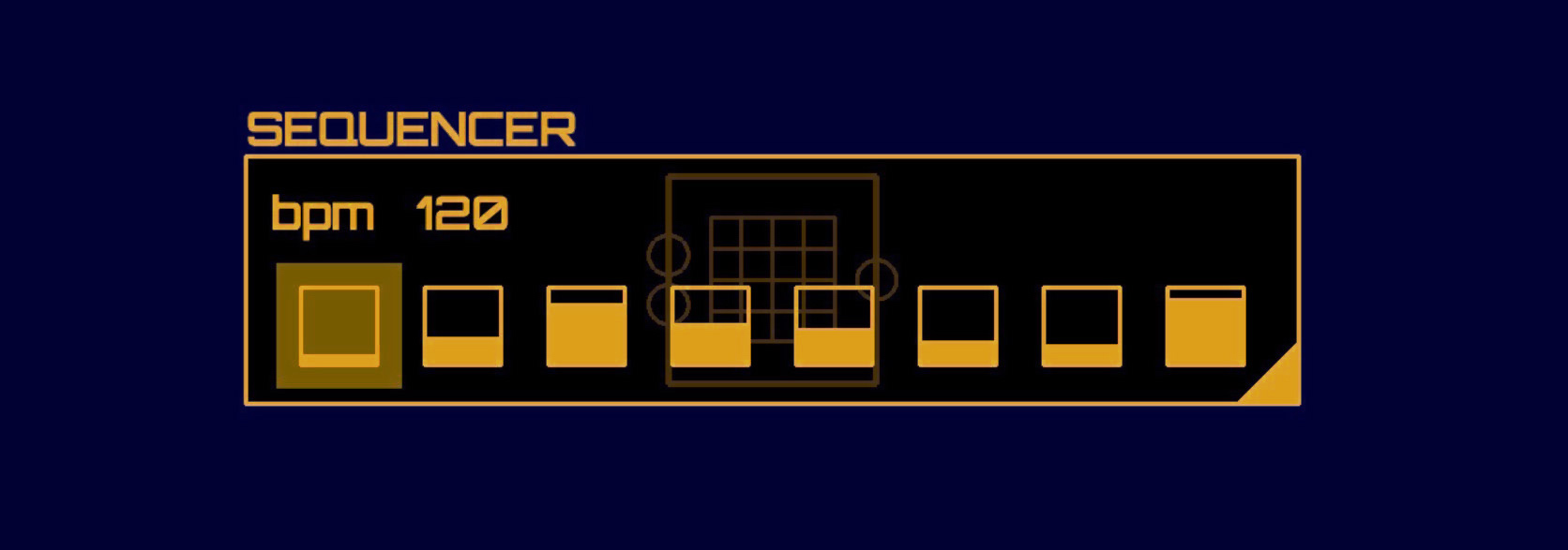
Sequencer
The Sequencer node (Figure 1.10) allows
the user to create sequences of arbitrary numbers of discrete steps,
where each step corresponds to a single numeric value between 0 and 1.
Using Add and Multiply these values can be
mapped to a desired range and used to control arbitrary parameters of
other nodes. Similar to many modular synthesis systems, the sequencer is
not intended solely to be used for note or percussion sequencing. Rather
it can be used to effect any discrete, time-varying parameter
change.
Sequencer
node.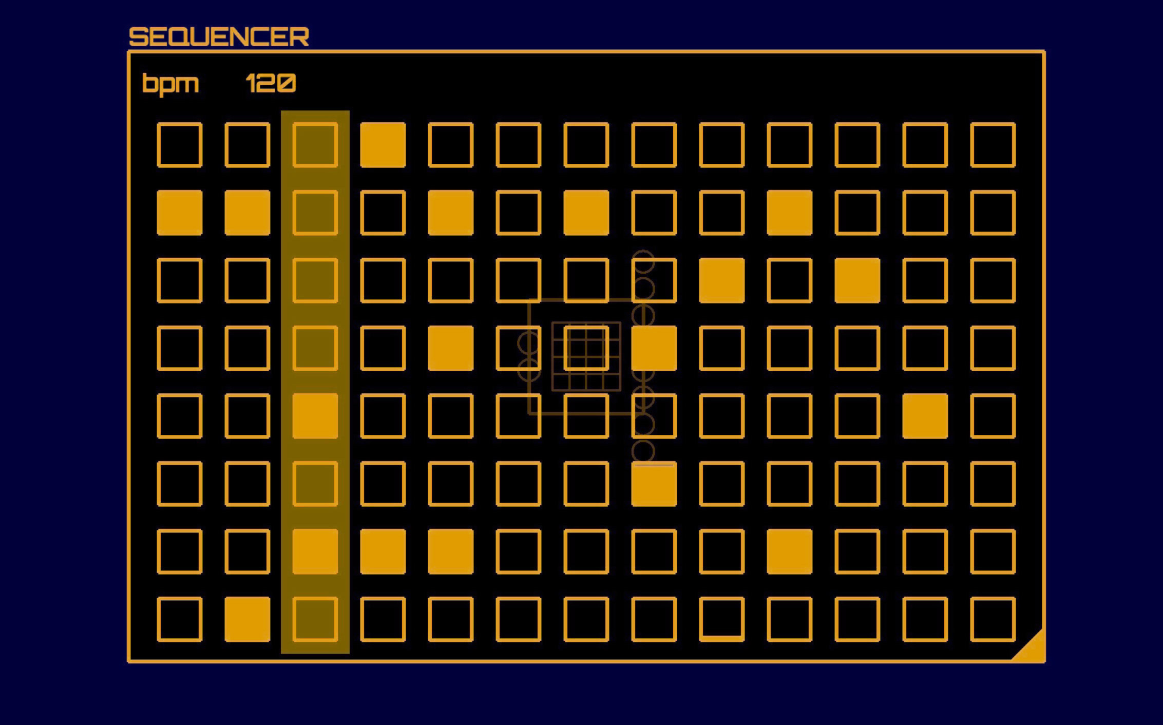
Sequencer node.By dragging a tab in the corner of the sequencer, the user can add
more steps or make additional rows (Figure 1.10); each
row is given an independent output. A shaded bar indicates the current
step in the Sequencer; as the Sequencer
advances the bar’s position is also updated. The step position is
automatically advanced according to the Sequencer’s
built-in BPM parameter, but can also be driven by an external control
input from a Timer node or another
Sequencer.
Each step corresponds to a value between 0 and 1. The specific value can be adjusted by touching a step and dragging it up or down. Quickly tapping a step will toggle it to 0 or 1, depending on its current state.
Orientation
The Orientation node outputs the host device’s
orientation in terms of Euler angles (pitch, roll, and yaw,
corresponding to rotation about the device’s x, y, and z axes,
respectively). Orientation data is sampled at 60 Hz, and represents a
composite of measurements from the device’s accelerometer, gyroscope,
and magnetometer. Add and Multiply nodes can
be used to scale these measurements to the desired range for musical
control. In this way, the Orientation node allows an
Auraglyph programmer to easily integrate motion sensing into their
program and utilize the gestural possibilities of mobile devices for
musical expression and performance.
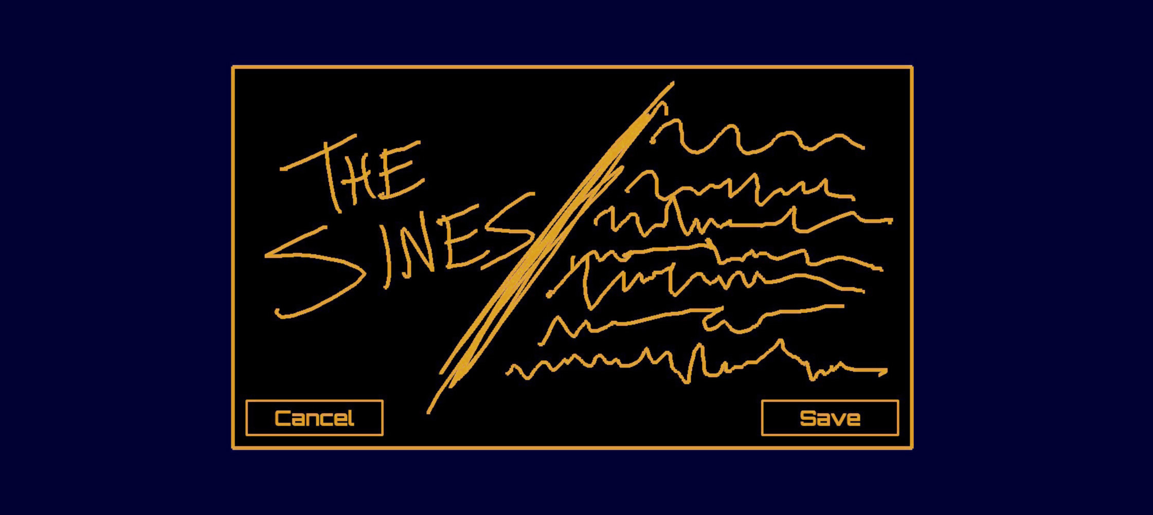
Document Management
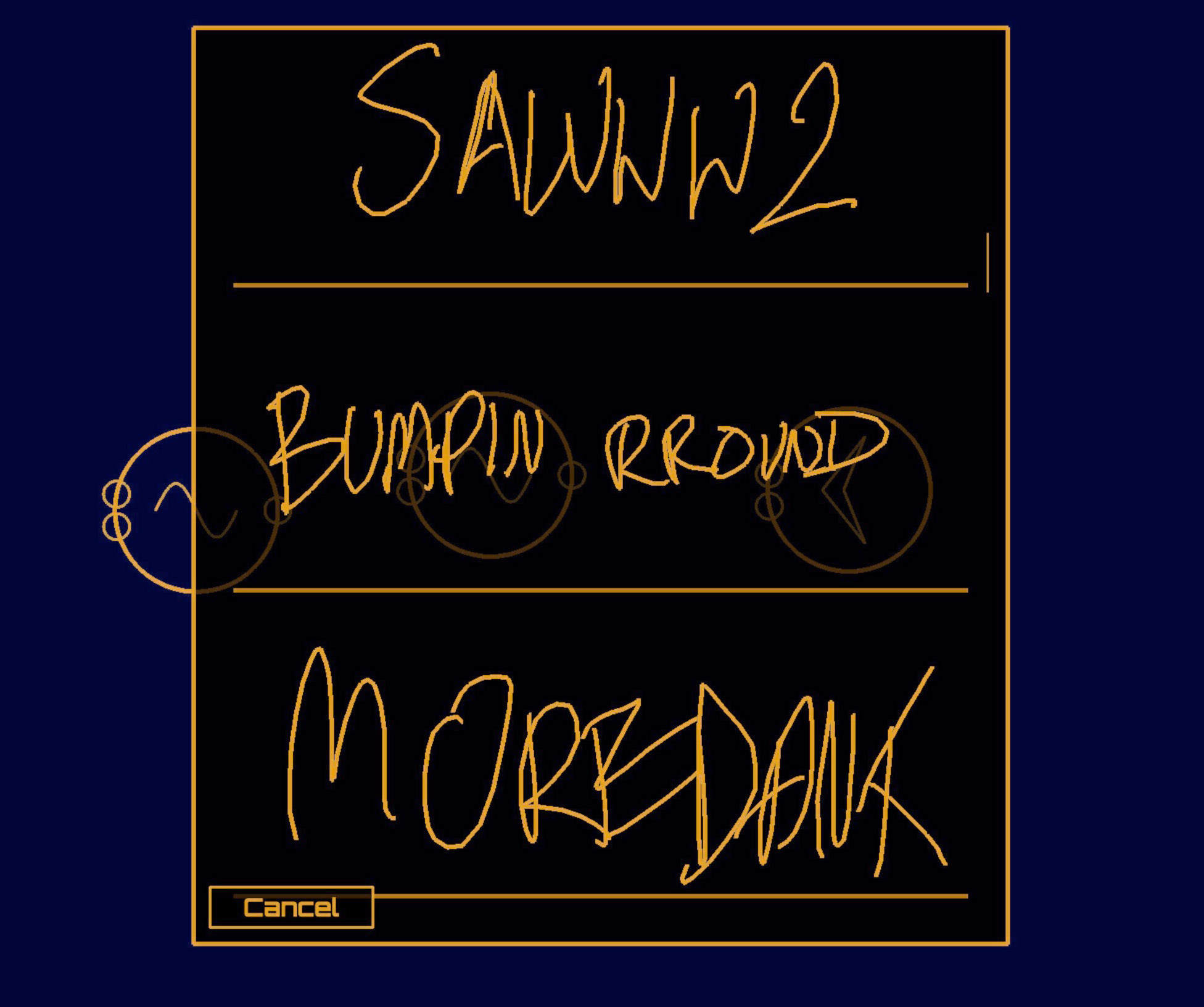
Auraglyph provides basic document management functionality, consisting of saving the current document, loading a previously saved document, or creating a new blank document. Upon saving a document, if it has not already been assigned a name, a popup will ask the user to give it one. The “name” is a freeform sketch that is drawn within the popup box (Figure 1.12), rather than a textual descriptor.
Requesting to load a document brings up a scrollable list of all of
the previously saved documents, displayed by name (Figure 1.13). Loading a document will clear
all of the current nodes and replace them with that of the previously
saved program. Creating a new program will simply clear all of the
current nodes, and add a single Output to start with.
User-Training the Handwriting Recognition System
The machine learning techniques Auraglyph uses to recognize written user input as node shapes or numerals require a training set from which it learns the distinguishing features of each shape (discussed in Handwriting Recognition). This training set consists of small number of example drawings of each type of shape that is meant to be recognized. The system has been initially seeded with a small training set drawn by the author. Thus, to a degree, it is tailored to how the author draws each type of shape. It would be preferable in the future for the base training set to represent a broader range of individuals, to better capture the variety of ways one might draw each shape.
To combat the limited nature of the initial training set, Auraglyph’s “Trainer” mode provides a simple interface to draw new examples and refine the recognition system. It is highly recommended that new Auraglyph users train the system with a few examples of each shape to ensure that the nuances of their particular writing style is factored in to the recognition system. But as the base training set is expanded to include more individuals the need for end users to update the examples themselves should diminish.
Visual Aesthetic and Dynamics
A core aspect of Auraglyph’s design is its unique and cohesive visual aesthetic. The decision is partly motivated by Wang’s “Principles of Visual Design for Computer Music” [10] (principle 10, “Aesthetic: have one”). To some extent this approach is also an effort to improve usability. By distinguishing itself stylistically from iOS’s default aesthetic and other contemporary visual design languages, Auraglyph suggests to the user that they are interacting with a system that is fundamentally different from what they may be used to, preparing them for further unfamiliarities. The uncommon design disarms users assumptions about how the software ought to operate, and in doing so eludes the need to abide by preexisting software conventions.
Auraglyph’s visual design aims to evoke memories of computer systems of ages past; its bright orange vector lines and blocky letters are inspired by personal computers of the 1980s. This is intended to add charm and personality to Auraglyph (number 9 in Wang’s principles of visual design), such that if parts of the software are difficult to learn or operate, at least its user has something interesting to look at. This historically-inspired visual style also harks back to a time when stylus-based computing was relatively common. Ivan Sutherland’s pioneering Sketchpad software, developed in 1963, used a light pen extensively for user input, and light pens were a common computer input device through the 1980s, such as with the Fairlight CMI music workstation or Iannis Xenakis’ UPIC. Auraglyph’s visual allusions to the past invite users to speculate an alternative technological history where pen input had survived and perhaps even become essential, in contrast to the real-world ascendancy of the mouse and keyboard.
Auraglyph goes to considerable lengths to ensure that its graphical motion and animation feels natural, smooth, and dynamic. The visual elements of Auraglyph do not simply appear or disappear; they fade in or fade out, expand and contract, or use more elaborate animations. Control-rate pings expand immediately and then slowly contract along an exponential slew. Starting from a single point, editor windows and other popup windows expand horizontally and then vertically before reaching their full size, in an animation resembling the GUIs of computer systems long passed into obsolescence (Figure 1.14). These visual flourishes are intended to imbue the software with personality and character, perhaps allowing its user feel comfortable with the more complicated aspects of the software.
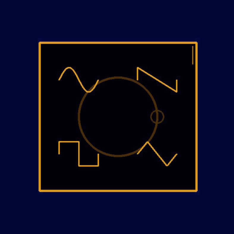
Color plays a crucial role in Auraglyph as well. The particular shade of orange used for most of the foreground graphics was selected due to its similarity to the monochromatic displays used in historical computer systems. The background color is not actually black, but a dark shade of navy, also selected as nostalgia for computer screens of the 1980s. Deviations from this monochromatic color scheme are few; occasionally a green color is used to indicate constructive actions (selecting an input port on for a node connection), while red indicates prohibited or destructive actions (breaking a node connection).
This visual identity is also a result of practical considerations. Auraglyph leans almost entirely on graphics rendered using the mobile variant of OpenGL (for reasons discussed in Implementation). OpenGL is markedly harder and more time-consuming to develop in than iOS’s native user interface toolkits. A spare graphical style has therefore been a necessity to facilitate rapid prototyping and iteration on interaction concepts without expending effort on graphics that may ultimately be discarded or heavily reworked.
Many elements of Auraglyph’s design serve both functional and aesthetic purposes. In aggregate, the waveforms displayed on the connections between audio nodes provide a high-level representation of the program’s current state. Individual waveforms indicate how each node in the program responds to its inputs, and can also reveal potential errors if a node’s output waveform looks wrong or is absent. An Auraglyph programmer can easily follow sound’s path through the program they’ve created, examining the effect of each node in real time. This information is passive, not demanding attention, but available to the programmer if they need it. The pulses visualized between control nodes serve similar functional purposes. From an aesthetic perspective, the waveforms themselves often possess a sort of natural beauty, especially as basic oscillators are modulated, filtered, enveloped, and processed by any number of any other means. As these waveforms and control pulses dance across the screen, an Auraglyph program’s visual display manifests a sort of living, breathing system that is, at times, as interesting as the sonic result.
Implementation
Auraglyph is implemented in C++ and Objective-C using standard iOS development frameworks and tools. Auraglyph uses a bespoke audio engine based on the unit generator model. As nodes are connected in the implementation layer, a directed graph is formed in the audio subsystem. Starting from the master output, destination nodes pull sample frames (in constant buffer-size increments) from each of their source nodes. Each node maintains a timestamp of the last frame it generated to avoid generating the same samples twice or jumping past the current global sample-time, in case two or more destination nodes pull from it.3 A destination node then maps samples from each of its sources to the corresponding input or parameter. Audio-rate destination nodes apply audio-rate source samples at audio rate, allowing its parameters to be modulated every sample, which is necessary to enable several important synthesis methods such as frequency modulation (FM) synthesis.
Control-rate processing occurs in a push-based system. As control-rate nodes produce new output values, they are pushed to each of their destination nodes. Control-rate destination nodes, upon receiving input, may then generate new output to push to further nodes. Audio-rate destination nodes apply incoming control-rate signals at audio buffer boundaries, linking the control rate to the audio buffer size. Auraglyph’s buffer size is currently fixed to 256 samples, or approximately 6 milliseconds at the fixed 44.1 kHz sample rate.
Auraglyph’s graphics are rendered using OpenGL ES 2.0.4 OpenGL graphics were chosen over higher-level GUI systems for a number of reasons. One of these was to enable a unique visual identity, as discussed in Visual Aesthetic. Most importantly, the flexibility of OpenGL allows experimentation with and creation of novel user interaction models. In contrast, existing GUI frameworks were believed to be too constraining. Many of the crucial visual effects employed by Auraglyph would be difficult to implement without a 3-D rendering system. Furthermore, OpenGL is a cross-platform framework, so building Auraglyph with it may facilitate porting the software to platforms beyond iOS, such as Android, Microsoft Surface, desktop platforms, or even virtual reality systems.
Auraglyph includes a number of different graphics rendering modes, as
implemented in a collection of OpenGL Shading Language (GLSL) programs.
A shader simply titled “Shader” is a basic 3D graphics
renderer. TexFont is used to display text characters that
have been prerendered to a graphics texture, serving as the workhorse of
Auraglyph’s text rendering system. The Clip shader is a
basic renderer that also supports defining a 2D clipping mask; contents
outside of this mask will not be drawn. This facilitates scrolling
content, where some extent of a visual structure may need to be drawn,
but its rendered form should not overflow the boundaries of its visual
container. The Waveform shader supports fast rendering of
audio waveforms. This shader receives its x, y, and z coordinates in
separate vertex buffers, so that one of these (typically y, e.g. height)
can be fed directly to the shader from a buffer of audio samples without
needing to repackage or copy the data.
Each available node type in Auraglyph is implemented as a C++ class
in the underlying source code. The C++ class for a given node type
provides code to render both its visual appearance and its audio or
control output. This enables a tight integration between the node’s
internal processing and its visual appearance, at the cost of having no
clear programmatic interface between the two. Input/output nodes also
have separate functions to render their appearance on the interface
layer. New nodes are added to Auraglyph by subclassing one of the
appropriate basic node types (implemented as AGAudioNode or
AGControlNode C++ classes) and overloading the virtual
functions used for graphical rendering and audio/control output.
Handwriting Recognition
It has been an explicit goal of this research to leverage existing tools and frameworks for handwriting recognition, rather than developing new software for this purpose. Auraglyph’s handwriting recognition is implemented using LipiTk [7], a comprehensive open-source project for handwriting recognition research. LipiTk is not natively designed to function with iPad applications, but we extended it to do so with straightforward code changes and additions.
LipiTk’s default configuration uses dynamic time warping (DTW) [8] and nearest-neighbor classification (k-NN) to match pen strokes to a preexisting training set of possible figures. The result of this procedure is one or more “most likely” matches along with confidence ratings for each match. We have found the speed and accuracy of LipiTk in this configuration to be satisfactory for real-time usage, though a slight, noticeable delay exists between finishing a stroke and the successful recognition of that stroke.
Before they can be used to classify figures of unknown types, the recognition algorithms incorporated into LipiTk must be primed with a set of “training examples” for each possible figure to be matched. This training set is typically created by test users before the software is released, who draw multiple renditions of each figure into a specialized training program. This training program serializes the salient features of each figure into a database, which is distributed with the application itself.
In our experience, LipiTk’s recognition accuracy is highly linked to the quality, size, and diversity of the training set. For instance, a version of our handwriting database trained solely by right-handed users suffered reduced accuracy when used by a left-handed user. A comprehensive training set would need to encompass strokes from a range of individuals of varying handedness and writing style. Interestingly, though, LipiTk’s algorithms are able to adapt dynamically to new training examples. An advanced system might gradually adjust to a particular user’s handwriting eccentricities over time, forming an organically personalized software interaction. Auraglyph takes advantage of this feature to a small degree, allowing a user to add new training strokes via a separate training interface.
Summary
Auraglyph proposes a new model of interacting with sound synthesis structures, via handwritten stylus gestures and touch. Sketching is an intrinsic part of nearly all creative activities, and as such presents a powerful metaphor for a music programming system. Auraglyph thus employs a two-handed interaction in which synthesis and control structures are created with stylus input and then parameterized via touch.
Auraglyph includes a rich set of nodes for effecting audio processing and control that can be flexibly interconnected. Many of these leverage the distinct affordances of the device itself, including a drawn waveform editor, a multitouch sequencer, and an orientation sensing control. Auraglyph also allows user to draw freehand sketches that are left as-is to decorate and annotate a patch. Clean, monochrome visual forms and a distinct animation style give Auraglyph a unique and functional design aesthetic. Together, these characteristics leverage the distinguishing features of mobile touchscreen technology for the purpose of expressive music programming.
References
Copyright (c) 2017, 2023 by Spencer Salazar. All rights reserved.